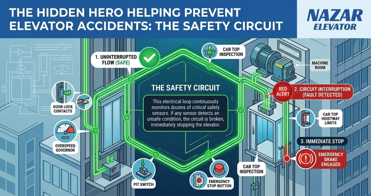
An elevator safety circuit is the electrical safety system that permits movement only when the required protective conditions are satisfied. When a monitored safety condition is lost, the system prevents starting or initiates the designed safety response. It connects the condition of doors and protective devices with the equipment that controls movement.
Passengers notice the cabin, lighting and buttons. The safety circuit usually remains out of sight, yet it helps determine whether a journey may begin and whether movement may continue. Calling it a hidden hero is appropriate, provided the description does not suggest that one circuit can prevent every accident. Elevator safety depends on coordinated electrical, mechanical and operational protections.
Table of contents
- What is the elevator safety circuit responsible for?
- How does a conventional safety chain work?
- Door interlocks: closing is not the same as locking
- Why the light curtain cannot replace a door lock
- Which devices participate in elevator protection?
- Overspeed governor, safety gear and the electrical circuit
- STO and the brake: two different jobs
- What changes with PESSRAL and electronic safety?
- Can an elevator move with its doors open?
- What does a safety-circuit fault actually tell you?
- Maintenance that preserves the protective function
- How EN 81-20 and EN 81-50 fit the subject
- Frequently asked questions
What is the elevator safety circuit responsible for?
The safety circuit answers a different question from the normal controller. The controller decides which floor to serve and how to manage a journey. The safety system determines whether the conditions required for that movement are present. A floor call alone must therefore never be enough to make an unsafe elevator run.
This distinction appears in the European Lifts Directive: Annex I, section 1.6.4, requires lift movement to depend on electrical safety devices in a separate electrical safety circuit. This is a functional safety requirement, not a universal wiring diagram. (EU Lifts Directive)
In a practical technical review, follow the whole protective function: the device detecting a condition, the circuit evaluating it and the final equipment preventing hazardous movement. A healthy input indication is only one part of that chain. The system must also produce the intended physical result.
How does a conventional safety chain work?
A conventional arrangement connects relevant safety contacts in series. Under the conditions required for normal travel, the chain is electrically complete. If a monitored contact opens, the permission associated with that chain is removed. Depending on the design, safety relays, contactors and drive safety inputs participate in the resulting response.
Consider an illustrative case: a landing door closes but its lock does not reach the required engaged position. The relevant electrical confirmation should remain unavailable, so a normal travel request cannot be accepted. The correct outcome is a refusal to run until the condition is resolved; the refusal itself does not identify why the lock failed to engage.
The series principle is useful because an open conductor can remove permission rather than silently preserve it. However, a short circuit across a device can conceal its opening. Safety design therefore has to address fault behaviour, installation integrity and the permitted architecture, not simply count the number of contacts. Certified electronic systems may implement functions differently from a traditional hardwired chain.
Door interlocks: closing is not the same as locking
A landing door must resist access to the shaft when the cabin is elsewhere. Its interlock combines a mechanical locking function with electrical monitoring of the required state. The car door has its own protective monitoring. These related functions should be described separately when reviewing an elevator control system.
During normal operation, the European directive requires landing doors to be closed and locked before movement starts, while also controlling when a landing door may open. Defined landing movements are an explicit exception under controlled conditions. (Door requirements in Annex I)
A door that looks closed may still have an engagement or alignment problem. Likewise, an electrical indication cannot establish that a badly adjusted mechanical lock has adequate engagement. For owners and purchasers, the useful question is whether both the locking mechanism and its electrical verification are correctly installed and checked.
Positive-opening door contacts are one established component category used in lift applications. Their mechanical contact-opening construction should not be confused with the ordinary switching action of any convenient sensor. Selection remains specific to the device and its certified application. (Schmersal door contacts)
Why the light curtain cannot replace a door lock
An elevator light curtain detects an obstruction in the door opening and interfaces with the door reopening function. A landing-door interlock establishes a different condition: whether the landing entrance is secured for the relevant operating state. The two functions complement each other. (CEDES reopening-device documentation)
This distinction matters during fault reporting. “The door reopens correctly” describes obstruction protection; it does not prove that the lock monitoring works. Conversely, a correctly monitored lock does not establish that the door detects an approaching passenger properly. Treating both as one generic door-safety feature can hide an important gap in inspection or procurement discussions.
Which devices participate in elevator protection?
The exact arrangement depends on the elevator design. The following distinctions help make drawings, quotations and maintenance reports easier to interpret.
| Device or function | Main purpose | Important distinction |
|---|---|---|
| Landing-door interlock | Secure the landing entrance and monitor its required state | More than a door-closed indication |
| Car-door contact | Monitor the required car-door condition | Separate from obstruction detection |
| Pit or car-top stop device | Initiate the specified stop function | Does not establish electrical isolation |
| Final travel-limit function | Protect against excessive travel at an end of the shaft | Separate from normal floor stopping |
| Overspeed governor and safety gear | Detect overspeed and provide the associated mechanical protection | Different devices with coordinated roles |
| Brake monitoring | Check specified brake-state feedback | Not necessarily a measurement of braking torque |
Electronic position supervisors can implement final-limit and inspection-limit functions within a defined safety architecture. Consequently, a modern installation does not necessarily use a separate mechanical switch for every function shown in an older diagram. (ELGO safety-function documentation)
The correct review compares required protective functions with the actual installation. Counting visible switches without understanding their role can be as misleading as assuming that a newer controller automatically covers every requirement.
Overspeed governor, safety gear and the electrical circuit
In a conventional traction arrangement, the overspeed governor responds to excessive speed and can actuate the safety gear through its associated mechanical system. The safety gear acts on the guide rails. An electrical overspeed contact can interrupt the safety chain; that electrical action and the mechanical stopping action have distinct roles. Manufacturer documentation illustrates these coordinated functions. (Dynatech governor documentation)
It is therefore inaccurate to say that the safety circuit itself grips the rails. It is equally inaccurate to assume that removing a motor command provides every protection against uncontrolled movement. The physical stopping and holding devices must be appropriate for the hazard and integrated with the detection system.
Unintended car movement, often abbreviated UCM, deserves separate attention. Movement away from a landing with doors open can create a hazard before a conventional overspeed condition occurs. A project should identify how that movement is detected, which element stops it and how the complete protective combination is validated. A generic “safety chain healthy” message does not answer those questions.
STO and the brake: two different jobs
Safe Torque Off, or STO, prevents the drive from generating motor torque through its safety function. STO does not provide electrical isolation or stop motion caused by an external force by itself. Drive manufacturers explicitly distinguish these limitations. (Danfoss STO guide)
In a traction elevator, the cabin and counterweight create a mechanical load system. Removing motor torque does not create a holding force. The brake and any other required protective devices must therefore perform their assigned functions as part of the validated design. The transition between drive operation and brake operation matters as much as the presence of either component.
Brake feedback also needs accurate interpretation. A switch or electronic monitor may confirm movement of a brake mechanism or a specified switching state. That is different from directly measuring the torque available at the friction surfaces. Mayr describes switching-state and armature-movement monitoring in its brake technology. (Mayr brake monitoring)
The engineering implication is straightforward: a satisfactory feedback signal should not be treated as a substitute for the brake inspections and functional checks required by its manufacturer. The statement “the brake is monitored” is incomplete unless the monitored condition is identified.
What changes with PESSRAL and electronic safety?
PESSRAL means programmable electronic systems in safety-related applications for lifts. In an appropriate assessed design, safety functions can use electronic processing and position information rather than rely exclusively on individually wired switches. The implementation must remain within its approved application and installation requirements.
For example, CEDES documents an iDiscovery and APS combination with functions including position-related monitoring and unintended-car-movement detection. These capabilities belong to the documented system configuration; they are not evidence that every electronic lift controller provides the same protection. (CEDES iDiscovery safety manual)
An ordinary CAN bus connection, PLC input or remote monitoring dashboard is not automatically a safety function. The relevant question is how the complete safety function handles faults, communication problems, configuration and its final outputs. Digital diagnostics can help explain events, but the protective action must not depend on someone noticing a notification.
Can an elevator move with its doors open?
During normal passenger travel, the door conditions required for movement must be satisfied. Some elevators also perform controlled levelling or re-levelling in a defined landing zone with doors open. The directive recognises this limited situation when levelling speed is controlled. (Controlled landing movements)
This explains why an absolute statement such as “any open door makes all movement impossible” is technically incomplete. The exception is a designed operating function with specific safeguards. It is not permission to defeat door protection for ordinary travel.
Inspection, emergency operation and rescue also have distinct requirements. Access to these modes and the movement they permit must follow the installation's documented procedures. Their existence must never justify an improvised connection across a protective device.
What does a safety-circuit fault actually tell you?
A safety-circuit message reports an observed condition, not necessarily a defective controller. A door lock, protective switch, connection, cable or monitored sequence may be involved. Useful diagnosis starts with the actual event: when it happened, the operating mode, the floor, the direction and the recorded sequence of signals.
Suppose an interruption appears repeatedly at one landing during door closing. That pattern suggests a different investigation from interruptions occurring at changing shaft positions during travel. These are diagnostic hypotheses, not confirmed causes. A competent technician must compare the observations with the installation drawings and manufacturer procedures.
Electrical ratings are also product-specific. ARKEL lists a 110–230 VAC safety-circuit voltage for the referenced ARCODE product. This example shows why a control circuit must not automatically be assumed to operate at harmless extra-low voltage. (ARKEL ARCODE specifications)
Repeated resets can erase useful context or restore operation without explaining the event. A good service record states the observed condition, confirmed cause, corrective work and verification performed before return to service.
Maintenance that preserves the protective function
Maintenance should address the complete relationship between mechanical condition and electrical confirmation. Door alignment, lock engagement, secure mounting, cable condition and the response of the control system belong in the same technical discussion. A continuity indication alone cannot establish the integrity of the whole elevator.
The UK HSE has warned specifically about platform lifts affected by poor door-component maintenance, inappropriate lock adjustment and interference with bypass switches. That bulletin concerns platform lifts; its evidence should not be relabelled as accident statistics for all passenger elevators. (HSE platform-lift safety bulletin)
For a maintenance contract or modernisation project, request clear answers about the protective functions covered, the equipment instructions used, the records retained and the process for resolving safety faults. Maintenance and independent examination also have different purposes. The applicable national framework determines their obligations and intervals; HSE guidance provides a UK example. (HSE lift-examination guidance)
Before accepting a replacement controller, ask the supplier to document compatibility with the installed doors, drive, brake, position system and safety devices. A component certificate does not by itself demonstrate that every interface in the assembled elevator has been correctly implemented.
How EN 81-20 and EN 81-50 fit the subject
EN 81-20:2020 covers construction and installation safety for new passenger and goods-passenger lifts within its scope. It provides the system context for discussing protective functions. (BSI EN 81-20 overview)
EN 81-50:2020 addresses design rules, calculations, examinations and tests of lift components referenced by relevant lift standards. It has a different role from EN 81-20. (BSI EN 81-50 overview)
These references should not become a blanket claim that every lift, platform or modernisation worldwide follows identical rules. The applicable jurisdiction, equipment classification, installation date and project scope must be established. The public overviews cited here explain the standards' scope; they do not reproduce their full technical requirements.
Frequently asked questions
Does a closed safety circuit prove that an elevator is completely safe?
No. It indicates the conditions represented by that circuit in its current state. Mechanical integrity, correct adjustment, fault detection and the performance of stopping devices still matter. Safety is assessed across the installation and its operating modes.
Does opening the circuit stop the cabin instantly?
No physical system stops in zero time or distance. The resulting movement depends on the validated safety response and the stopping equipment. A universal stopping-time claim would be misleading without the specific design and test conditions.
Can a fault be solved by permanently bridging a contact?
A bridge can conceal the condition the contact is intended to monitor. Restoring apparent availability this way does not repair the fault. The underlying problem must be identified and the original protective function restored through authorised work.
What should a building owner remember?
The elevator safety circuit helps turn protective conditions into permission to move. Its value comes from correct integration with doors, drive equipment, brakes and mechanical safeguards, supported by documented maintenance. A refusal to run can be evidence of a protective response and should be investigated accordingly.
Replacing a controller, a door operator or the safety devices on an existing lift is an engineering task, not a parts swap. Nazar Elevator manufactures complete elevator systems and modernisation packages at its facilities in Konya and İzmir, Turkey.